21+ Led Clock Circuit Diagram Pics. A digital clock is shown named as circuit diagram of digital clock using counters! To design this led binary clock circuit, we have chosen the online eda tool called easyeda.
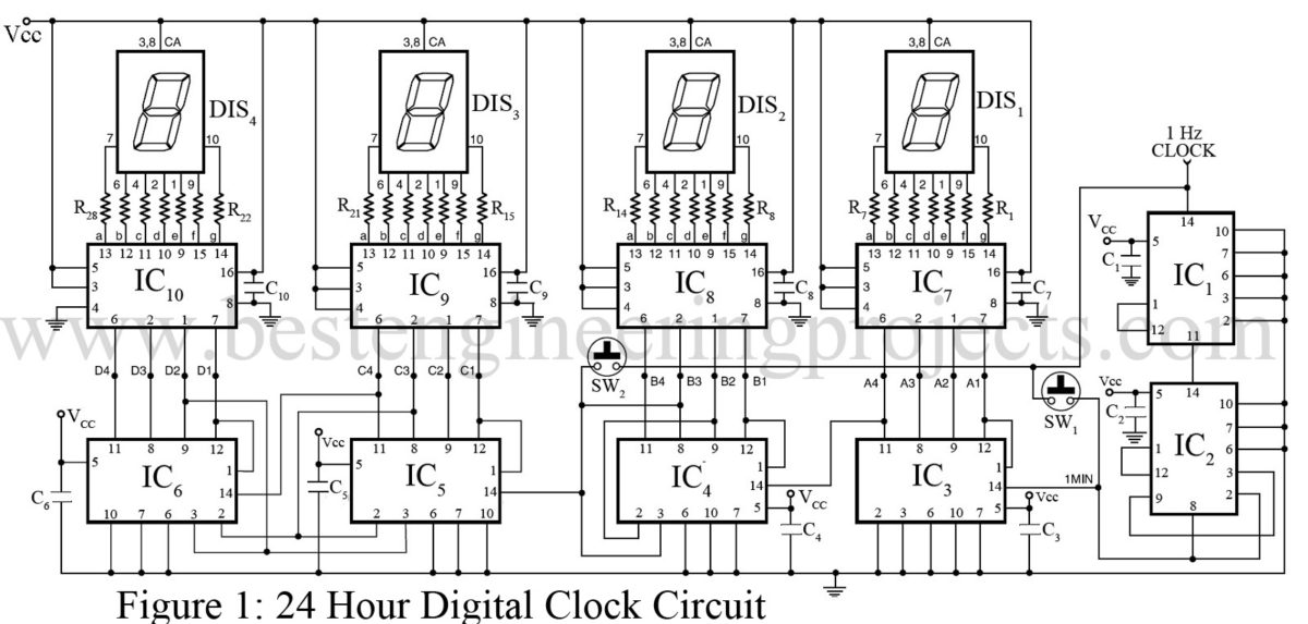
24 Hour Digital Clock and Timer Circuit - Engineering Projects from bestengineeringprojects.com This ic gives 10 outputs according to the clock pulse it receives from the clock input, which is pin 14. The circuit needs clock signal to increment the counts, this is provided by the below circuit which outputs 1 pulse every minute. Here's a circuit diagram for the power supply and time base.
These circuits and projects have already been tested.
This is the circuit diagram of digital clock based on ic mm5314n. The power supply and time base circuitry is the same as described in the 28 led clock circuit above. The clock display uses 6 pieces of 7 segment led with format hh:mm:ss. Led drive control special circuit.

0 Response to "Led Clock Circuit Diagram"
Post a Comment