21+ Ldr Switch Circuit Diagram PNG. As we know bc547 transistor switched on when its base to emitter voltage ≥0.7 v and will be off if. Ldr switches are used to switch a relay or other device when light are present or absent.
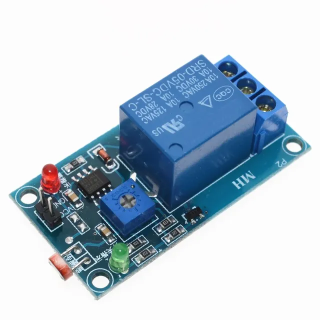
5V Light Photoswitch Sensor Switch LDR Photoresistor Relay ... from ae01.alicdn.com In this ldr darkness sensor circuit ldr (light dependent resistor) is used to sensing the light and darkness. Dvd & amp circuit diagrams. Here are some diy ldr switch circuits available on our website and the web.
Light switches are using the main component of triac and ldr.
The sensor circuit purpose is used to detect any near by objects. This light activated switch based on national semiconductors comparator ic lm 311 and ldr. This is the circuit diagram of a light activated switch based on national semiconductors comparator ic lm 311 and a ldr. Building a simple light detecting circuit is very easy.

0 Response to "Ldr Switch Circuit Diagram"
Post a Comment