Ladder Logic Diagram For Elevator
Get Ladder Logic Diagram For Elevator Images. Study elevator plc ladder logic. Each device in the relay rack would be represented by a symbol on the ladder diagram with connections between those devices shown.
Ladder diagrams (sometimes called ladder logic) are a type of electrical notation and symbology frequently used to illustrate how electromechanical switches and relays are interconnected.
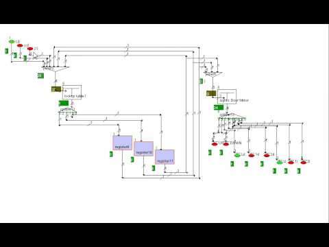
In the ladder diagram there are two vertical lines where the left vertical line is connected to the positive voltage source of the power supply and the right line is connected to the negative voltage autocade simples for ladder logic: Ladder logic program of a 4 levels traction elevator. The developed ladder logic has been implemented by ladder diagram programming the required inputs and outputs of the elevator for moving forward and reverse, door opening and closing and motor operation have been included in the logic and interpreted in addition to that implementation of. Ladder logic was originally a written method to document the design and construction of relay racks as used in manufacturing and process control.

0 Response to "Ladder Logic Diagram For Elevator"
Post a Comment