Led With Sensor Wiring Diagram
16+ Led With Sensor Wiring Diagram Background. Ir sensor circuit basically consist an ir led and a photodiode, this pair is generally called ir pair or photo coupler. If you want to display it on lcd, you can follow the second wiring diagram and upload the code water level with led alarms and buzzer with level distance and temp on lcd.
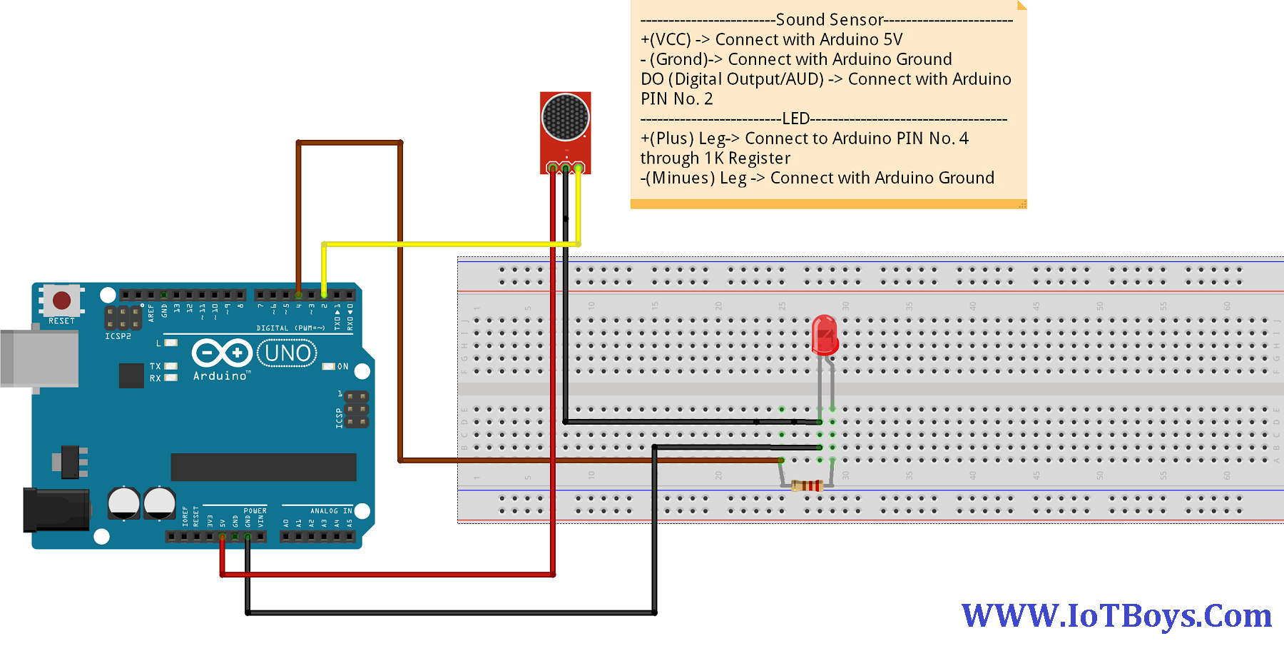
New users may wish to follow one of the wiring diagrams.
The longer wires on the leds are positive and the shorter wires are negative. Npn type low level output mode, o9~12 have the maximum drive current 170ma.o13~16 50ma max. Wire a remote sensor to operate light fixtures anywhere around the house. If the circuit has diodes, reverse the two leads and check again.

0 Response to "Led With Sensor Wiring Diagram"
Post a Comment