View Latching Circuit Ladder Diagram Images. Each device in the relay rack would be represented by a symbol on the ladder diagram with connections between those devices shown. With ladder diagrams no attempt figure 11.2 shows an example of a ladder diagram for a circuit that is used to start and stop a motor using push buttons.
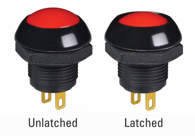
Otto showcases their new P9 latching push button switches ... from cdn6.bigcommerce.com Output y is set (latched) indefinitely. Ladder diagrams (sometimes called ladder logic) are a type of electrical notation and symbology frequently used to illustrate how electromechanical horizontal lines in a ladder diagram are called rungs, each one representing a unique parallel circuit branch between the poles of the power supply. From that, i understand that it's just a lock and latch.
Note that the stop contacts x401 are shown as being programmed as open.
You can use any transistor in this circuit, just it will need to find proper ressistance value accordingly. This soft latching power switch circuit design contain only two transistor, resistors and momentary push button switches,so this is one of the cheapest way to get your work done. The diagrams are latched circuits using the rst and set instructions. If input a goes true momentarily then the set symbol changes the state of output y to true.

0 Response to "Latching Circuit Ladder Diagram"
Post a Comment