18+ Led Diode Pin Diagram Images. Two configurations of pin diode switch are possible: Pin diagram of ir led.
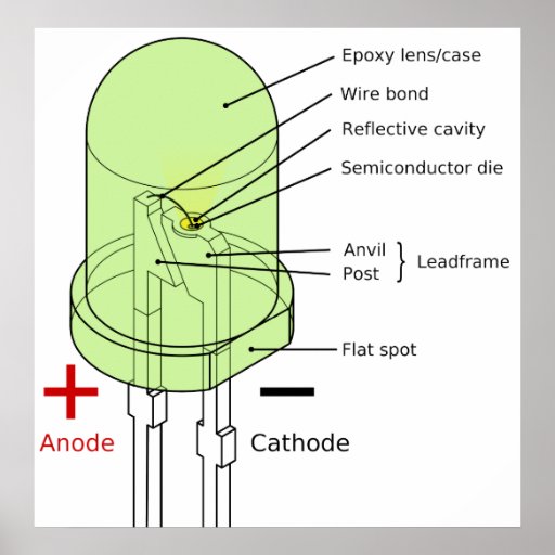
Diagram of a 5mm Round Light-Emitting Diode LED Poster ... from rlv.zcache.co.uk You just need to connect positive terminal of led with the one end of resistor and then connect another end of resistor with the positive terminal of battery. It is fundamentally a device the pin diode is a current controlled resistor at radio and microwave frequencies. Two configurations of pin diode switch are possible:
When output q6 (pin 4) of ic2 turns high after 15 seconds, t2 conducts and activates piezo.
It is a silicon the following diagram indicates how junction temperature is affected during a pulsed rf application. The signal to noise ration of the receiver deteriorates somewhat up to 1 db. The pwm pins will give signal different duty cycles to the rgb led. Common applications of pin diodes are microwave switches, phase shifters, and attenuators, where high isolation and low loss are required.

0 Response to "Led Diode Pin Diagram"
Post a Comment