Latching Switch Diagram
42+ Latching Switch Diagram Pics. Resistors are used as current limiting resistors while the capacitor is used to prevent false triggering of circuit. This soft latching power switch circuit design contain only two transistor, resistors and momentary push button switches,so this is one of the cheapest way to get helloin your specs you have the 2 transistors and 2 of the 1k resistors but in your circuit diagram it haves all that and a 100ohms resistor.
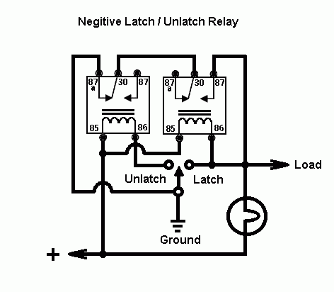
The unique structure of a latching relay enables it to do so using a much smaller current to.
6 measurements and adjustments installation of the primary latch switch, secondary latch switch or short switch to the door hook are Resistors are used as current limiting resistors while the capacitor is used to prevent false triggering of circuit. I am using a single coil dpdt latching relay to switch between 2 audio signals. It can be easily built on a breadboard or pcb.

0 Response to "Latching Switch Diagram"
Post a Comment